Gold Cylindrical Optical Fiber
Fiber Lab Report
By Aditya Mittal
Spring 2005
Contents:
Background
·
Objective
·
Methodology
·
Optical Fiber
·
Mathematical
Model
The Experiment
·
Procedure
o
Preparing glass
for deposition
o
Preparing the
Vacuum Chamber
o
Evaporation System
and Deposition Process
o
Fiber Redraw
Process
o
Collapsing
Process
o
Attaching the
hangs
o
Fiber Drawing
Process
·
Conclusion and
Further Experiment
Credits
·
Acknowledgements
·
References
Background:
Objective:
Fabricating very thin metal film,
specifically, 99.9% pure gold films about 5nm thick for this experiment.
Methodology:
This shall be done by using a
new fabricating process to fabricate a smooth gold film at the core-cladding
boundary in fiber. The process consists
of depositing gold onto a clean glass rod which will form the core of the
fiber, collapsing a glass tube or ampoule
to create the preform, and then
drawing the preform into optical fiber
with a drawing tower. In the process of
pulling the fiber we also end up pulling the gold into a thin film.
Optical Fiber:
Optical Fiber is a flexible
optically transparent fiber, usually made of glass or plastic, through which
light can be transmitted by successive internal reflections. The fiber consists of a core, a cladding, and
a buffer coating as shown:
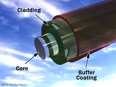
Parts of a single optical fiber image from http://electronics.howstuffworks.com/fiber-optic1.htm
(Tuesday May 10, 2005)
Mathematical Model:
We can think of metals as ‘a
sea of mobile electrons’ as electrons flow freely throughout a metal. So, we can model an extremely thin sheet of
metal as free electron gas. In quantum
mechanics the most primitive model of electron gas was constructed by
Sommerfield who basically treated the solid as an infinite square well in 3D. The electrons were free to move around
inside, i.e. zero potential inside and infinite potential outside.
Then, Bloch complicated the
theory a little by also including the periodic potential inside created by the
positively charged nuclei. Although,
neither model considers electron-electron repulsion, they do show the
importance of the Pauli Exclusion Principle (no two fermions have identical
quantum numbers) in explaining the ‘solidity’ of a metal. That is since electrons are fermions they do
not simply settle in ground state and occupy volume as only 2 electrons can
occupy a state.
Assuming there is no
excitation of electrons we can then determine the free electron density of a solid, i.e. the number of free electrons
per unit volume. The boundary separating
the occupied states from unoccupied ones is called the Fermi Surface and the energy corresponding to the free electron gas
is the Fermi Energy.
Analogous to internal thermal
energy, quantum mechanical energy also exerts pressure on the walls from inside
of the metal and keeps the metal from collapsing. One main task in our model then is to
determine the Fermi energy. We model the
thin gold film on the core-cladding boundary as a ‘metal cylinder fiber’ using
collective modes of electrons. From that
it turns out that the Fermi Energy can be determined using the following
equation, where N is the surface density of electrons in the thin metal film
and n = 1, 2, 3…. The U(k) has the form of kinetic energy with an effective
mass.

where ![]() and
and ![]()
For the metal cylinder fiber
model first the relative dielectric constant’s real and imaginary parts are
calculated using Kramer Kronig Relation.
This constant depends on the oscillating frequency and wave vector of
light. Two factors contribute to the
surface charge density for this thin metal.
One is the electron distribution and the other is the positively charged
ion background. Given the distribution
and using normal quantum mechanical means discussed above the Fermi energy is
then calculated. Also, from the
equations of the dielectric constant the plasma frequency of the thin metal
film is calculated and further the indices of refraction are mapped as a
function of wavelength in gold films of different thicknesses such as 2.06 or
4nm. Following are the graphs for the
two thicknesses:
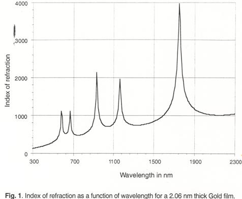
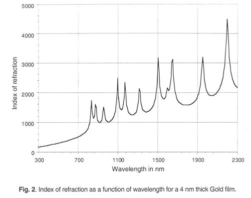
Graphs and Fermi Energy equations borrowed from Mathematical
Model of Metal Cylinder Fiber
The
Experiment
Procedure:
Preparing glass for deposition:
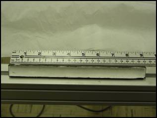
We start with a cutting and
cleaning a glass rod of 7056 type glass of 1mm diameter. The Redraw process explained later is then
used to reduce the diameter of this rod to 0.5mm.
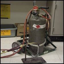
Preparing the Vacuum Chamber:
Vacuum is created in a
chamber using a Vacuum Diffusion Pump
(Vapor Jet Pump) like the one pictured:
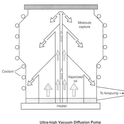
Picture borrowed from Inside a Vacuum Diffusion Pump
Such a pump can create a
vacuum down to 10-10 torr in pressure. However, before this pump can begin its work,
another pump, called the roughing or forepump is used to reduce pressure down
to 10-3 torr in the glass chamber.
At this point the vaccum diffusion pump is started and the pressure
starts to drop below 10-3 torr.
The reason for this is that the diffusion pump cannot exhaust directly
to atmospheric pressure and so the forepump is used to maintain proper
discharge pressure conditions.
The way this pump works is
that there are three jet assemblies of
diminishing sizes as shown in the picture with an oil at the base. A heater vaporizes the oil that exits from
these jet assemblies and is suddenly cooled by the surrounding coolant,
specifically liquid nitrogen in our case which is poured into the system when
creating a vacuum. Liquid nitrogen has a
temperature of -196 degrees Celsius.
“The droplets of oil coming down may actually exceed the speed of sound,
but there is no sonic boom, largely because the molecules in partial vacuum are
too far apart to transmit the sound energy.”
(Joaquim 3) This very high
velocity jet stream conveys a downward motion on the molecules bringing them
towards the forepump outlet where the gases are removed by the forepump and the
condensed oil begins another cycle. Advantages
of using this pump are that it is one of the most reliable ways of creating a
10-3 to 10-8 torr vacuum, it lasts for more than thirty
years and it has no mechanical parts.
Using this pumping system we
are able to remove all unwanted material from inside our evaporation
system. This evaporation system is used
for depositing gold onto our glass rod.
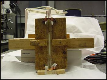
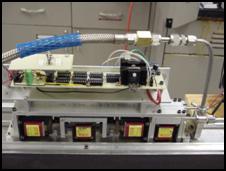
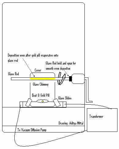
Evaporation System and Deposition Process:
The evaporation system is
depicted in the diagram. The evaporation
occurs inside a vacuum chamber so that there are no impurities in the
deposition on the glass rod. In our
experiment a new glass chimney was created by cutting a larger glass beaker in
order to achieve a longer length of rod onto which deposition occurs. This would allow for ease in making the hangs
and drawing the fiber in latter steps.
In the chimney, two notches are cut out to allow the glass rod to go
through while supporting its cover. At
the bottom glass slides cover any additional openings at the interface of the
chimney and the parts that hold the boat
in place. The boat is a small container
to hold the gold pill that will be evaporated onto the glass rod.
In our experiment the glass
rod was held by a pencil lead holder cut out from a mechanical pencil as it is
able to grasp such a thin rod well and keep it in place during the deposition.
Although, the heater at the
bottom ensures that gold will evaporate straight up giving a smooth continuous
deposition it is necessary to use the chimney to protect the vacuum chamber
from being coated with gold. As we saw,
our chimney also got gold deposition in the process.
Although, the spinning of the
glass rod was automated, a manual pedal was attached with the system to ensure
the glass rod stayed spinning. In case
it stopped it could be restarted with this pedal. Having to restart the experiment for such a
small cause would be time costly.
After ensuring a clean vacuum
chamber the above described setup is created. Then the chamber is closed and
sealed airtight. Then liquid nitrogen is poured into the system to act as the
coolant. After this the forepump is
turned on and the pressure is dropped to 10-3 torr. The foreline might have to be opened and
closed many times to achieve this. Next,
the vaccum diffusion pump drops the pressure down further. After everything is ready, and the vacuum has
been created, the deposition process begins by heating the boat by passing a
large current through it (120 Amps at about 3V AC). Within a matter of about 30 seconds the gold
evaporates from the boat and a thin film is seen on the glass rod and
chimney. These are the most exciting 30
seconds in the whole deposition process.
Fiber Redraw Process:
This process is used to
reduce the diameter of a glass rod from say 1mm to 0.5mm. Essentially, a heater called the redraw
furnace is used in which the glass rod goes through and at the bottom a weight
is hung. The weight applies the force on
the rod by which it is pulled into the desired diameter. The glass rod is held in a small hole made in
a rubber cork to grip the glass rod tightly.
Based on the temperature dependence of the viscosity of the glass the
redraw process can be modeled mathematically.
Important factors include the type of glass being used, the initial
diameter and rod length, furnace temperature, and amount of weight hung. Viscosity is given in Pascal-seconds and the
following points are defined as the temperature at which the particular glass
has a certain viscosity: Strain Point
(1013.5Pa-s), Annealing Point (1012Pa-s), Softening Point
(106.6 x Density/(2500kg/m3) Pa-s), and Working Point (103Pa-s). Although, this process has been explained
here, it occurs before deposition to adjust the diameter of the glass rod on
which gold is deposited.
Collapsing Process:
So far, we have been working
with just a glass rod. Collapsing is the
process by which we enclose this solid glass rod inside a glass tube. In our experiment the inside rod has a
diameter of .5mm and the tube has a .8mm inner diameter (ID) and 4mm outer
diameter (OD). Stuffing the glass rod
inside this tube creates the ampoule
that is then collapsed to form the preform
that we pull with the drawing tower.
After, the fiber is formed this outer tube forms the cladding and the
inner rod forms the core. Clearly, the
gold deposition on the inner rod will then form a smooth gold film at the
core-cladding boundary in the fiber.
Firstly, a tube is sealed off
on one end using a torch to flame the glass.
While using the torch it should always be remembered that the gas should
always be opened first before lighting the torch and should not be left on for
too long without lighting it. Sealing
one end ensures that the glass rod inside will not fall out.
Next, the glass rod is
inserted inside the tube and after creating a vacuum in this tube it is
“pinched-off” using the torch. It is
important that the interface between the cladding and core is a complete vacuum
except the smooth gold film. During pinch-off
the glass tube should be sealed on both ends.
The ampoule is now ready to
be collapsed. Firstly, it is enclosed
inside a so-called bomb. It is this bomb that is placed first inside
the pre-heat furnace and then pushed into the collapsing furnace. The pre-heat furnace heats the bomb to about
360 degrees and then the bomb is pushed further in where it rests until it gets
to about 630 degrees Celsius in the collapsing furnace. It is kept at 630 degrees for about 30
seconds and then pulled back into the pre-heat furnace for annealing that is to subject the glass to a process of heating and
slow cooling in order to toughen and reduce brittleness. At this time the preheat furnace is set to
about 450 degrees Celsius. The bomb is
allowed to sit in the pre-heat furnace for 8 to 10 hours and is then taken
out. At this point, we have a single
piece of glass rod which has the gold film trapped in between the core and
cladding. After cooling it to room
temperature, the collapsing process should be repeated a few more times in
order to get an extremely stress resistant fiber.
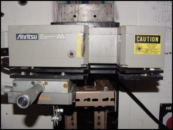
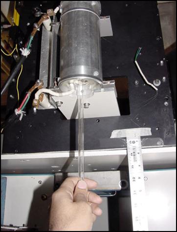
Attaching the hangs:
Before the preform can be
attached to the drawing tower to be pulled, handles or hangs must be attached
to it to hold it on the tower. For the
purpose of attaching the hangs there is a special machine that holds the
preform and handle being attached and rotates them and allows horizontal
movement by spinning the wheel to bring them closer or move them farther
apart. The machine is depicted below.
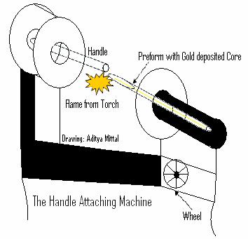
The two main things to keep
in mind for this part are that the glass used for the handle must be the same
as the glass with which the fiber is being made. Otherwise, the glass cracks in the process of
melting the handle and fiber together.
The other thing is that the torch is hottest when a short hard blue
oxidizing flame is seen. This is the
kind of flame that should be used for this part in order to prevent blackening
of the rods and a strong attachment.
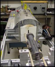
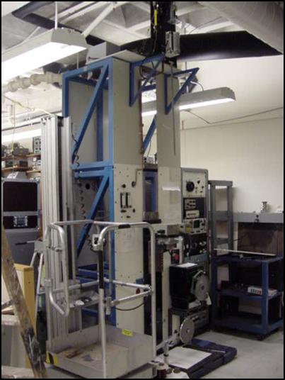
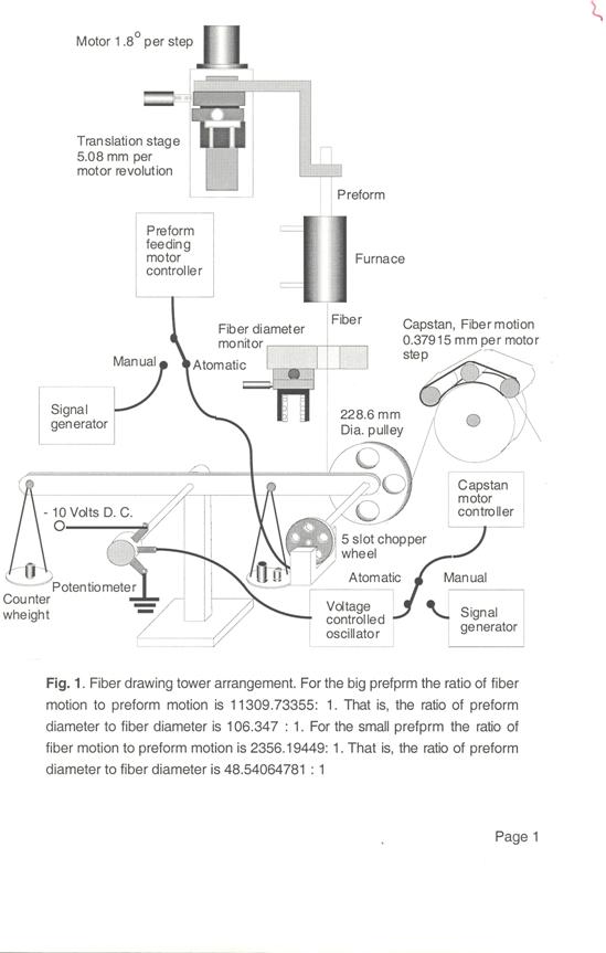
Fiber Drawing Process:
This is the final step in the
experiment. The drawing tower is
depicted in the diagram. The preform is
hung at the top and comes down through the furnace. Time must be taken to carefully set up the
fiber in the center so that it would come straight down through the furnace at
the top of the drawing tower and not touch the heating coil of the
furnace. The furnace is set at about 640
degrees Celsius which is the temperature at which the glass we used melts. The melting point of 24 carat gold used is
higher so that wouldn’t melt and accumulate in one place when using this temperature
for drawing the fiber. While the upper
handle is attached to the top to hang the preform, the lower handle has a small
mass attached to it to help the fiber get pulled down by the force of
gravity. This process will extrude the
gold which will be of nanometer thickness.
Slowly, the fiber begins to
come down and the rate at which the fiber came down increases
consistently. In about an hour and a
half we had some length of fiber with gold at the core-cladding interface. The fiber is then attached to the pulley to
maintain constant pressure and thus an even diameter and the fiber can then be
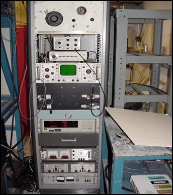
collected on the spools at the bottom.
Attached with the tower is a laser operated monitor that determines the
diameter of the falling fiber. In
addition to that the furnace temperature is also constantly monitored.
Conclusion and Further Experiment:
In our experiment, a problem occurred that the thin gold tore in places giving a gold deposited region in the fiber and then a region where clear glass could be seen and the pattern continued through the thin fiber. It was contemplated by Dr. Kornreich that perhaps the problem could be resolved by pulling a glass with a higher melting point at a higher temperature as the glass would flow more slowly and smoothly. Melting at a higher temperature also implied using a metal that would melt at a higher temperature than pure gold. Gold had been chosen because it is highly malleable. Therefore, it was determined that the new metal could be a gold alloy that has a higher melting point than that of pure gold. That is the next experiment in line.
Credits:
Acknowledgements:
Special
thanks to Dr. Phillip Kornreich
for involving me with this gorgeous project of his, sharing his ideas and research
with me, supporting my interests in the learning of science and mathematics,
and maintaining an extremely caring approach.
Also,
special thanks to graduate student Ramesh Narayanan for all the
insightful discussions and help with gathering information for this paper, and
to Zheng-Xuan Lai for getting me started on things in
lab. It has also been nice knowing Akshob
Bangle and Jim Flattery while working in the lab.
References and
Sharma, Halme,
and Butusov. 1981. Optical Fiber Systems and Their Components.
Griffiths, David
J. 2005.
Introduction to Quantum Mechanics.
Shankar, R. 1994. Principles
of Quantum Mechanics.
Redraw Process. Revised: 24 March 2003.
Mathematical Model of Metal Cylinder Fiber.
Joaquim and Foley. Inside a Vaccum Diffusion Pump. http://xtronix.com/Diffusion%20Pump.pdf#search='operation%20of%20a%20vacuum%20chamber%20and%20pump'. Santovac Fluids, Inc. and Varian, Inc., Vacuum Technologies. 8 May 2005.
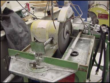
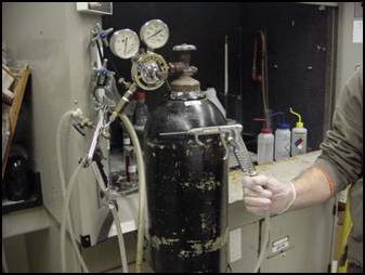
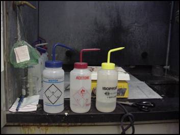
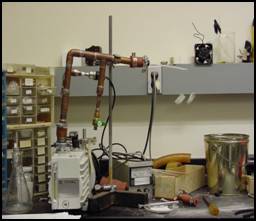
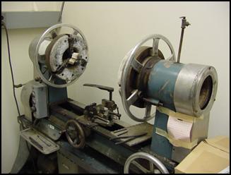
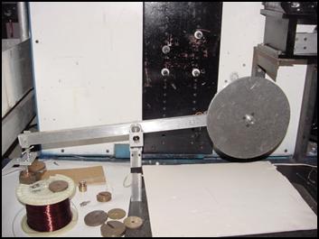
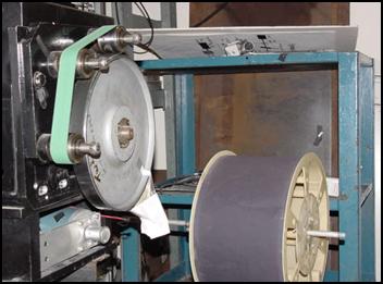
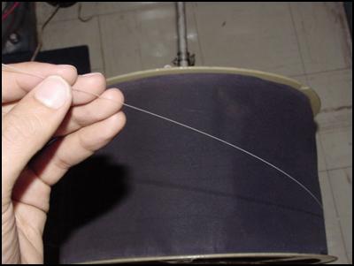
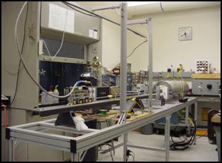
Extra Pictures of Our Lab: